


1. Introduction
Modern civilization is maintained by essential components like water and energy. However, increase in population, depletion of natural resources and increase in global warming have given rise to water and energy scarcities. By 2025 about 20% of the countries will suffer severe problems in water shortage and there will be a lack of access to safe drinking water to about 2.7 billion people, as estimated by the United Nations [1]. It is also predicted that 50, 114 and 52 years are the respective years for oil, coal and gas depletion times. It is known that it consumes a large amount of energy for treatment of water and wastewater, and that both chemical and thermal energy are contained in wastewater. For wastewater, organic compounds generally remain for particular heating systems at temperatures higher than tap water. A variety of wastewater treatment techniques, such as heat pumps and anaerobic digestion, can potentially be used to restore energy consumption [2]. Sustainable technologies are, therefore, the most relevant in addressing the problems of resource scarcity and environmental protection in energy-efficient wastewater treatment and wastewater generation. Microbial electrochemical technologies are evolving to collect energy using electrically active bacteria (EABs) [3]. The MESs are beneficial compared to conventional biology treatment technologies due to their various forms of energy recovery and less sludge generation. MESs mainly promote wastewater disposal and energy recovery. Yet high-quality effluents will not suffice to achieve flexibility and future reuse. In comparison to conventional wastewater treatment systems, this form of integrated MESs has shown an increase in energy recovery and efficiency [4-6]. For example, with the ultrafiltration membrane MFC using the flux-through type microbial fuel cell, 90% of the Chemical Oxygen Demand (COD) and 97% of the total coliform were eliminated [5]. MES becomes more efficient in terms of energy generation and wastewater treatment by introducing membrane-based technologies. Thus, in order to give a clear view of the investigation in this area, a thorough examination of this new development relating to MES technologies is needed.
Many studies of MES technologies have been published so far. The main focus of the previous reviews, however, is mainly on individual technologies among various membrane-based MESs (Microbial Technologies [MTs]). These separate approaches could not provide a full picture of the latest trends in new technologies which show different options for integrating different membrane technologies with MES. The objective of the current review is to evaluate all MES-MT on the basis of the latest papers. The specification in terms of theory and implementation of MES-MT are described in detail in terms of design, performance and important operational factors. In addition to discussing the barriers to exploit the full potential of MES-MTs, current problems have also been addressed, including low biodegradability of wastewater, sluggish marine desalination levels, upscaling issues, and membrane-related issues including fouling [7,8].
2. Classification of MES-MTs
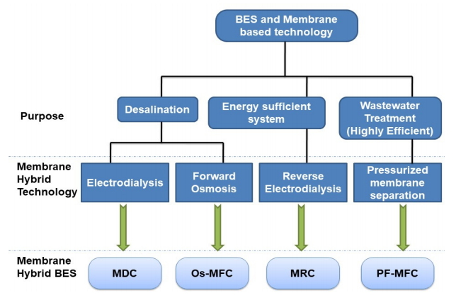
For systematic review, there are four types of MES-MTs: microbial desalination cells or MDCs, microbial reverse electrodialysis cells or MRCs, microbial combustible fuel cells or Os-MFCs and pressurized microbial modification cells or PF-MFC as illustrated in Fig. 1. In MESs i.e. MDCs and Os-MFCs, two types of MES were developed for the removal of salinity. In the first example, the membrane-based electrical-electrodialytical ion exchange technology was hybridized to create MDC, which is a desalination technology [6]. MDC can be used for generating energy from wastewater and at the same time for desalinating marine water by producing bioelectric power. The second case includes forward osmosis and a MES for Os-MFC processing [9]. A reverse electrodialysis (RED) stack has been built into the MES, which is an IEM system used to recycle salinity grading energy, with the goal of building MRCs to improve energy self-sustainability and energy generation [4]. Ultimately, the combination of UF membranes with pore size 0.01-0.1 microfiltration membrane, or pore size 0.1-1.0 mm MF with MESs was intended for high effective wastewater treatment system with a pressure filtration system such as dynamic membranes or DMs over pore size 1.0 µm. Together, such structures are called PF-MFCs. 2009 was the first year since MES-MT's public interest grew with the publication of the MDC report. A total of 188 research papers, including 115 MDC papers, 20 MRC-specific research papers, 19 Os-MFC specific papers and 34 PF-MFC-specific research papers, were published on water filtration by pressure, desalination or salinity induced control. Originally, the study of the MES-MT values was under emphasis [4,8,9]. Numerous studies have since been conducted to achieve realistic MES-MT applications like cell design [10-13], study of the mechanism of ion transport [14,15], chemistry processing [16,17], and actual applications usefulness [18,19], operating conditions [20], and reduction of befouling and upscaling [21-24].
3. MES-MT theory and operation
3.1. Microbial Desalination Cells (MDCs)
3.1.1. Microbial desalination cells basic principles
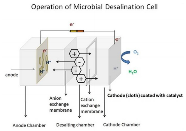
In comparison to standard MFCs, an extra chamber in MDCs is normally seen between cathode and the anode chamber, for salt water desalination. An anion exchange and a cation exchange membrane (AEM and CEM) are used as opposed to the three MDC chambers [6]. The organic compounds are degraded into electrons and protons by an EAB present in the anode chamber. The anion and cation in the desalinisation chamber are transported to the anode chamber and cathode chamber via AEM and CEM simultaneously with the electron transfer to maintain the net electrical charge balance of the MDC process [21]. Then the electron receivers are moved via the external chamber into cathodes. This system enables MDCs, without any external energy source, to generate electricity and simultaneously desalinate water. Removal of salinity is pre-dominant attribute to current generation over 70% according to a previous study [18], i.e. transfer of electron between the anode and cathode. The efficiency of desalination can be increased if the current generation can be upgraded [22]. In addition to current generations, salinity dialysis and water transportation through IEMs play a role as the driving force behind desalination in MDCs [18,23]; Mehanna et al. has shown that a decrease in total dissolved solids or TDS up to 43 percent is caused by dialysis, and Jacobson et al. has shown that saltwater TDS has been reduced to about 42 percent [18].
3.1.2. Microbial desalination cell development and functional factors
3.1.2.1. Configuration of the reactor
A general MDC is rectangular and comprises three chambers as shown in Fig. 2 [6]. There are several limitations to rectangular three chambered MDCs like collection of chloride ions in the anode chamber and imbalance in pH between anode and cathode chambers. Many studies have suggested changes in MDC designs to overcome these limitations. Jacobson. al. developed the tubular up-flow MDC for the improvement of the efficiency of desalination by continuous operation via membrane surface expansion to promote ion exchange [10]. Multiple desalinization chambers were installed in the MDCs in addition to improving the desalination rate. The overall desalination rate was increased, with the removal of more ion pairs for every electron transfer to the cathode of anode, but with the increase in ohmic resistance, the current generation decreased [24]. The stacked MDCs have, therefore, provided a higher efficiency in desalination and power density to overcome this issue, using very thin waste disposal pills which minimized ohmic resistance [25]. Due to the blockage of ion transport from the anode to cathode chambers via desalination chambers, a number of decreases and increases in pH were recorded in the 3 chambered MDC anode and cathode chambers [26]. In order to prevent sharp pH-change in anode and cathode chambers a direct proton transmission pathway was implemented in a MDC, thereby developing rMDC [27]. The activity of rMDC proceeded with neutral pH of the electrolyte whereby, relative to the traditional MDC, the rMDC displayed an improved peak power density (779-931 mW/m2) and COD removal levels of 78-79%. It was also shown by Luo et al. that rMDC could be increased by 152 percent and 98 percent respectively in contrast to those in the traditional MDC. In rMDCs, however, cathodic catalyst operation may be inhibited by bacterial growth of the cathode-electrode.
In order to reduce the direct build-up of biofilm on the cathode electrode, the stack rMDC was used by Chen et al. with a cathode device with a glass fiber separator [28], Another challenge could be the accumulation of chloride ions in the anode chamber which could inhibit the effectiveness of EAB, although some conflicting results have been reported [16,29,30]. Through adding a bipolar membrane or BPM, which is micro-based desalination electrolysis cell for chemical production or MEDCC, Chen designed an additional chamber between the anode and the cathode chambers [17]. The chloride ions pass from the desalination chambers are deposited in the container facing the BPM. The normal pH decrease was successfully avoided within the anode chamber and the aggregation of chlorine ions, with acid formed in the chamber facing BPM. In addition, it was possible to adjust the output of MEDCCs by various middle chamber architectures, including concentration chamber, desalination and acid chamber [31,32]. An alternate MDC configuration was modified to modulate anode and cathode chamber ion migration and pH difference through the application of a capacitive de-ionizing or CDI to a MDC [11]. The MDC is called a capacitive microbial desalination cell or a tweaked MCDC. The MCDC consisted of two electrode-membrane CDI units, containing a nickel/copper screen, a copper fabric and a MRE, into anode, cathode and desalination spaces. Physical and electrical absorption of ions was used for the desalination of salt water during the process and the protons produced may move to the cathodic chamber. The osmotic movement of water is one of the driving forces in MDCs for desalination [33]. In order to enhance the transport through osmosis of water, Zhan and He developed osmotic microbial desalination or Os-MDC cell to substitute FO membrane with AEM [34]. In order to remove ionic species and nitrate in groundwater in situ, a submergible modular MDC system made up of a cathode and anode chamber called a microbial desalination-denitrification cell or SMDDC was created [35]. AEM and CEM were used in both anode and cathode cases. Wastewater, anodes and nitrates are circulated throughout the pipeline and ultimately used to absorb electrons. Ping and He [36] have also implemented a modular MDC concept.
The MDC architecture is spatially separated from the anode and cathode chambers to the system as a decoupling MDC. In the anode chamber two AEMs were mounted, the cathode assembly consisted of two CEMs and a cathode electrode comprising one MDC. In terms of construction and equipment repair facilities, the MDC decoupler is more versatile than standard MDC structures. The emphasis on denitrification and regeneration is the latest established MDC architecture. Multi-step MDC consists of several cathode chambers, anode and concentration chambers, which denitrify industrial wastewater by using biological reactions and electrical migration as wastewater continually flows through several anode and cathode chambers [37]. Furthermore, a MDC comprising biological cathode and MF hollow fiber tubes, called HFM-MDC, achieves outstanding nitrification and productivity in nutrient recovery [38].
3.1.2.2. Biocatalyst and anode electrode
A number of studies have been conducted to improve the efficiency of MDCs with new anode electrodes for MDCs. During the experiment carried out by Sophia and Bhalambaal, the anode shell was filled with a granular coconut shell [39]. The photocatalyst nanostructured hemetitis was mounted one side of the anode chamber of a MDC on a graphite layer. With regard to the maximum current density and salt removal efficiency, due to the photocatalyst anode growth power, the conventional MDC has been overtaken by a photo-microbe desalination cell [40]. In MDC's MFCs are stimulated to create a biocatalyst for anode electrode of the mixed cultures that are obtained by anaerobic sludge or anode chambers. However, due to different anode conditions, i.e. a high salinity, MFC's bacterial population composition is distinct from MDC's [41]. Actinobacteria and Chlamydiae are the main species in the early stage of the activity of the MDC of anodic bacterial communities, as Lou et al. suggested, with more bacterial species found after long-term operations [42]. The major species in the anodic microbial population are Proteobacteria, verified by Zhang that the anodic bacterial culture in the MFCs is broadly varied than the bacterial MDCs [43]. Nevertheless, more recent research has shown the dominant EAB to be Pseudomonas and Acinetobacter. Several studies have shown various types of MDC inoculum. Bacillus subtilis moh3 species have been inoculated by Sabina in MDC to handle waste oil from waste engines using MDC [44]. Two commercial colouring bacterial strains-B, the Aeromonas subtilis was also used for Moh 3 and Hydrophila subsp. More recently, the DL1 strain of Geobacter sulfurreducens for the MDC has been used by Borjas et al. [45]. The MDC anode was used to filter wastewater from a steel plant and the Pseudomonas putida and the activated sludge [46].
3.1.2.3. Desalination chambers and membranes
For conventional MDCs, only one AEM and CEM are fitted. The IEMs also require the differentiation of anode, cathode and desalination chambers in the desalination space [47]. Unless better IEMs were developed the efficiency of the MDCs could not be increased. In contrast with commercial IEMs, for example, Mehanna produced non-market IEMs that increased the desalination rate and power density of MDCs because the IEMs produced were significantly improved with ion exchange capacities and a lower thickness. In another analysis, two CEMs (i.e. CMI-7000 and Nafion 117) that have been integrated into the MDCs were assessed [23]. It was shown that the MDC equipped with a membrane Nafion has better desalination than the CMI-7000 [48]. The broader desalination in the MDC using a Nafion membrane was exacerbated by the greater movement of water from the cathode chamber into the desalination tank with water osmosis. AEM based on non-patterned quaternary ammonium poly (2, 6-demethyl 1, 4-ohenylene) oxide has been used in MDC mixed for the improvement of MDC performance [49]. The existence of IER's and several cell pairs were investigated in addition to the beneficial element for the chamber of desalination (e.g. space between membranes) [22,31]. The maximum distance of desalination was 1.5 mm in diameter for MEDCC's with varying widths of chamber (e.g., 1.5 mm, 3 mm, 6 mm, 9 mm, and 12 mm) [31]. The same findings were confirmed by Lu et al. [50]. Because of the low salt concentration in the desalination region, MDCs are subject to high internal resistance. In a desalination tank, an IER is installed to desalinate low saltwater volumes [51]. As Morel has shown, in contrast to historically designed IDC MDCs with IERs (R-MDCs), desalination rate was significantly higher (50%-800%) [51]. Installation of desalination chamber separators is investigated into the effect on the interior resistance of stacked microbial electro deionization or SMEDIC, carried out by Shehab et al. Turbious flow with desalination stacks is usually installed to make sure the water is equally distributed across membrane surfaces [52]. The elevated distances reduced SMEDIC's performance by increasing internal testing resistance. The SMEDIC spacers could not and did not perform ion migration by IEMs.
Maximization of desalination chambers is also important as a key factor in the development of MDCs is the number of desalination cells. There have been recent studies on the effect of MDC efficiency by Ge et al. [22] and Chen et al. [53] in several desalination chambers. The stacked MDCs were run by Gen et al. with different chambers for desalination (e.g. 1, 2, 4, 6, 8, 10) [22]. The efficiency of charging (from 113% to 450%) and desalinating processes (from 28.5 mg/h to 90.8 mg/h) is increasing with the MDC with more cell variations with the solution of 35 g/L of sodium chloride. Nevertheless, Chen et al. [53] analyzed multiple pairs of 100-mL stacked MDCs between 6 and 14. The current desalination ration was also increased in the stacked MDCs of increasing cells of desalination. Nonetheless, the highest charge transfer rate and the average desalination frequency (323 mg/h) were observed in the stacking MDC of 10 desalination cell pairs. More water leakage from the dilution chamber into the concentration chamber occurred through more cell pairs in stacked MDCs. Furthermore, the internal resistance was improved due to additional chambers in the concentration chambers. Higher numbers of cell pairs demonstrated both benefits and drawbacks. Together, fewer cell architectures for efficient MDC operations are suggested taking the findings into account.
3.1.2.4. Electron acceptor and cathode electrode
The first MDC developed by Cao for the development of a MDC cathode compartment used carbon felt as the cathode electrode. The MDC has not employed a suitable metal catalyst due to the use of ferric cyanide as an electron acceptor [6]. In action, however, cathodic ferricyanide reductions were inacceptable, since platinum coated carbon paper produced air cathode MDCs. Nonetheless, the oxygen of an electron acceptor is essential to use a high-value metal catalyst such as platinum to increase the cost of capital for MDCs [23]. As a result, an algal biocathode and photosynthesis biocathode is applied to micro-organism inoculate. A nominal voltage of 609 mV is given by the MDC biocathode and its salinity is 92% greater than that of MDC's 35 g/L air cathode. The oxygen supplied by the algae was then used in the photosynthetic biocathode MDC/P-MDC as an electron acceptor. This photosynthesis biocathode is more effective and environmentally friendly due to its versatility in the absorption and removal of carbon dioxide [54]. Nevertheless, the P-MDC showed no positive desalination [43]. The performance of MDC declined considerably during long-term operations. The FE-C-N catalyst and an increased performance of the FE-N-C catalyst were recently tested on the MDC cathode [55]. Ozone has recently also been studied as a conventional electron receiver along with ferricyanide and oxygen due to its high redox potential. In MDCs with ozone cathode, the desalination rates were higher than in MDCs with oxygen cathode [56].
3.1.2.5. Factors affecting the MDC operations
Substrate is crucial for the anode’s working. Mehanna et al. measured the findings at various substrate concentrations: the maximum power densities were lower than 1 g/L acetate but increased desalination performance in MDCs supplied with 2 g/L acetate [23]. Anodic bacteria’s activity in MDCs was obstructed by the excess build-up of substrates. Further desalination efficiency with increased running time can be obtained. Lu et al. [57] considered a less salinized and less current MDC with less COD (350 mg/L) than a high COD (500 mph/L). Furthermore, it shows that the MDC is less usual with lower COD. The growth of anodized bacteria can also be affected by low substrate concentration. Therefore, the optimal availability of substratum volumes for MDC output is important. In the majority of MDC work, acetate was used as a basis, although different kinds of organic carbon sources were used. The results are similar to those of a two-chamber MFC, as Luo et al. [42] have tested a wastewater substratum for MDCs. The MDC was supplied with sod chloride saltwater and sodium bicarbonate in its desalination tank, a density 4 times better, while COD was extracted more effectively 52 percent, which contributed to a 66 percent increased desalination rate. A MDC of five chambers, an anode chamber, two cathodic chambers and two desalination cabins was also provided with the dewatered sludge [22]. Many studies have been conducted to evaluate the petroleum wastewater extraction as a MDC working substrate [58]. Therefore, household wastewater, waste steel mills, sewage sludge and industrial wastewater are other MDC substrates used. Like other MESs for complex carbon compounds, MDCs also have low degradation efficiencies. The efficiency of the anolyte buffer was also calculated as an operational component specific to the anode; a pH decrease in anode chambers may also be due to the inhibition of the metabolism of anode-bacteria. Catholyte effluent with high pH fixed by a previous MDC process was applied to the buffer power. In another study, by adding a tamper solution to the anode chambers, the present output and salt extraction rates of the MDC is increased. The activity factor for cathodes is typically related to catholic factors such as concentration, form and buffer efficiency [59]. Certain MDC tests, including MFCs, involved phosphate buffer and ferricyanide solution. Although MDCs can achieve a higher efficiency than PBS or ferricyanide, MDCs running costs are higher when these methods are used as cathode. The use of substitute catholytes is not appropriate, such as acidic water, wastewater effluent from MDC anode, PBS blend, salt water or seawater per se. PBS is only 3% when we use acidized water and PBS in MDCs with similar performance. A low concentration mixture of PBS and saline water, according to a recent study, could be another good option for the MDC catholytes.
Factors like hydraulic retention or HRT and components were also analyzed as well as initial concentrations. Various factors have been discussed in Table 1 in comparison to different types of MDC configurations. During the early desalination phases, the consistency of energy recovery, the anodic microbial structure and desalination rate were also determined by the salt water concentration. Hydrogen or MEC modified MDC systems prevailed with 20 g/L sodium chloride, 29% G. sulfurreducens and 5% G. sulfurreducen and 63% Pilobacterpropionicus. Nevertheless, as a result of a more recent study which showed greater power density production, the first salt concentration is enhanced by increasing the conductivity of desalination chambers and anode together with increased IEM interconnection potentials by the concentration levels of three chambered MDCs [16]. Nevertheless, ionic concentration in the desalination chambers has been shown to significantly influence the efficiency of desalination. The up-flow MDCs using seawater showed considerably reduced power density and desalination efficiency. Sodium chloride and bio-sodium bicarbonate have also been used in desalination reservoirs. Because of the transport of bicarbonate in the desalinating chamber during the MDC process, the buffer efficacy and conductivity of wastewater increased compared to conventional MFCs. The effect on the output of divalent ions MDC's was analyzed by Luo and Zuo et al. [14,60]. In the case of divalent anions like bromide and sulfate ions, the performance of MDCs was not significantly affected while in the presence of divalent cations such as magnetic or calcium ions, the performance of divalent ions on IEMs surfaces was considerably diminished. In recent years, only-value cations like sodium and potassium ions have a slower motion than divalent cations such as calcium and magnesium ions because of the reduced ionic pressure of monovalent cations [15].
3.2. Osmotic Microbial Fuel Cell (Os-MFC)
3.2.1. The fundamental principle of osmotic microbial fuel cells
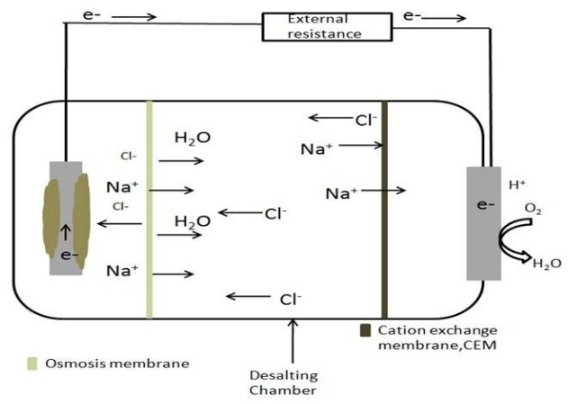
A mixture of FO and MFC has been developed to provide clean water. A traditional two-MFC container design is similar to Os-MFC, but instead of an IEM membrane, a FO membrane divides the chamber as shown in Fig. 3. The Os-MFC anode chamber is filled with wastewater with low conductivity, like the feed solution, and fitted with EAB electrode anode. A cathode that absorbs high levels of salt water. Os-MFCs follow the same description with respect to the other MESs. The osmotic pressure between the cathode and the anode chamber produces clean water from the salt water on a FO membrane when electricity is generated through the combination of the anodic oxidizing reaction through cathode reduction with the EAB. The power generation in Os-MFCs is improved compared with traditional IEM-based MFCs [9,13,61,62]. Zhu et al. reported increasing proton transmission via the membrane and FO membrane selectivity via the water flux [61]. Qin also showed an important factor in increasing Os-MFC production due to the reduction in membrane flux tolerance. Also in Os-MFCs high electricity was generated, although there was no water flow from the multiple membranes due to increased plate polarization as a result of the promotion of ion transfer via the fouled membrane [62].
3.2.2. Osmotic microbial fuel cell design and operating factors.
Os-MFCs are designed from modified 2-chambered MFCs. While it seems important to maximize Os-MFC's water flow and electricity generation, most of the previous studies have failed to improve the configuration of Os-MFC. Regarding enhancing Os-MFC’s efficiency, Werner [13] and Al-Mamun [63] have attempted to use the micro air transmitter in the marine aerobic biomass cathode. Nevertheless, a considerable number of membranes, which are a key component of OS-MFC design, have been researched in conjunction with FO membranes; Os-MFC and FA procedures have different internal conditions. For FO processes with Os-MFCs, the high-performance membrane may not always function well. For use with OS-MFC, Yang [64] has tested three different types of FO membranes. A polyamide membrane was more flexible in the FO processes than a standard CTA (Commercial Cellulose Triacetate) membrane provided by Hydration Technology Innovations, USA. Nevertheless, both in terms of power production and water flows, in the Os-MFC membrane CTA ES were higher because of the increased level of diffusion on the PA membrane. Furthermore, the effect of Os-MFC performance on the FO membrane orientation was assessed.
A higher flow of water and the reverse flow of the solution are recorded for the membrane guidance for the feed solution (AL-FS), in comparison to the feed solution support layer (SL-FS) [65]. Yang [66] further stated that the Os-MFC water flow with CTA SL-FS membrane NW was increased, despite the fact that the FO membrane orientation did not have a considerable influence on Os-MFC's electricity generated. The study has found that an OS-MFC with SL-FS has a lower water flow than an AL-FS. In Os-MFC, Ge and He [20] were tested for the correct catholyte (such as sodium chloride, calcium chloride, PBS and glucose), using various types of catholyte. The current production and water flow of PBS are better than the general solutions for sodium chloride. The solution acidified by sodium chloride (pH of 2) was also obtained in the same condition as the drawn solution in Os-MFCs. The solution for acidized sodium chloride was considerably cheaper than the PBS solution; thus, the acidified solution for sodium chloride was considered to be the best alternative for Os-MFCs. Qin et al. has recently analyzed the influence of catholyte pH and reported a decline in the current generation, as higher catholyte pH leads to higher losses [67].
3.2.3. Performance: COD removal and desalination
MDC itself could not amplify the desalination process hence MDCs combined with other membrane technologies were introduced (Table 2). These membrane technologies include FO membrane technology and DD membrane technology that produced much better results than MDC alone. The DD technology was mainly used for the elimination of boron from desalinated water for better growth of plants [68], it removed around 52% - 60% of boron from the water. When MDC alone was used it resulted in less elimination of boron elements and also led to salt accumulation. In case of a MDC combined with FO membrane the volume of wastewater decreased by 64% and almost doubled the production of electricity as both the systems provided electricity [69]. Overall, the combination of these formed an Os-MDC setup that showed better results than each of the technologies used separately. It produced more electricity, more of removal of COD but produced less volume of wastewater hence it was used for pre-desalination of high saline water or brackish water. It became economically, environmentally and energy-saving technology [70]. In a salt solution (35 g/L NaCl), COD removal percentage was found to be 70.6% and conductivity reduction of 94% was obtained.
3.3. Microbial Electrolysis - Desalination Integrated System (MEDC)
Microbial Desalination Cells were integrated with Microbial Electrolysis Cells (MECs) to produce hydrogen, simultaneously treating the wastewater and water desalination. The integration was constructed by splitting the cell into 3 compartments with the help of ion exchange membranes [71]. Moreover, this type of integration was utilized to investigate the process of triple wastewater treatment, with the primary motive; removing metals from industrial effluent, desalinating water along with the removal of nitrogen from municipal water [72]. Another type of modification was constructed by integrating FO (Forward Osmosis) and MDC for treating artificial wastewater along with desalinating water [73].
3.3.1. MEDC performance for desalination and hydrogen production
Based on various integrated modifications, there are several applications and products. MEDC modification is constructed by integrating MEC and MDC for COD removal and desalinating water along with hydrogen production. According to Lu et al. [71], a MEDC could achieve the maximum desalination rate (10 g/L NaCl) of 98.80% along with producing hydrogen at a rate of 1.5 m3/m3 d which proportionally equivalent to 1.6 L/h at the cathodic chamber at applied potential of 0.8 V. A similar type of integration was constructed by Li et al. [72] for wastewater treatment along with water desalination and removal of nitrogen from seawater resulting in maximum nitrogen removal rate of 4.07 mg/L. This type of modification, integrating nitrogen removal helped overcome the major drawback of conventional MDC i.e. pH fluctuations leading to desalination at the rate of 63.7% along with the electricity production of 293.7 mW/m3 which is further utilized for metal removal in MEC which resulted in 99.50% of lead (II) removal in 2 days operation. Another type of modification was constructed by Zhang et al. [73] through integration of Osmotic Microbial Fuel Cells (Os-MFCs) and MDCs for enhancing the desalination rates along with high removal rates of organics and salts in comparison to the conventional MDC, resulting in desalination rate of 96% along with electricity production of 160 Wh/m3.
3.4. Pressurized filtration-microbial fuel cells
PF-MFCs are related to as the Principle of Pressure Filter-Microbial Power Cells, Microbial electrochemical Membrane Reactors (BEMRs) [74] and Electrochemical Bioreactor Membrane (EMBRs) [75], MFC Membrane Bioreactor (MFC-MBRs) [76] and UF-MFCs [5]. PF-MFCs shall be deferred to according to the filtration membrane type built and the reactor configuration. Nevertheless, the same rules apply to all PF-MFCs. Remember that, in addition to the filtration membrane, the basic design of a PF MFC is almost similar to that of a conventional MFC. For the treatment of anodal wastewater EAB uses porous membranes, including DM's, MF-membranes and UF-membranes, while bio-anode oxidation and cathode reaction incorporate organic waste energy recovery. A low hydraulic pressure is needed for wastewater purification. PF-MFCs remove COD, oxygen, reactive suspended solids, bacteria and viruses from the same concepts and therefore produce higher quality final effluents than typical MFCs [77].
3.4.1. Design and working factors of microbial fuel cells for pressurized filtration
During most of these experiments, new architectural configurations were developed [5,76,78,79]. Consequently, PF-MFC generated different configurations. The FFMFC is classified into three main groups: 1) the aerobic cathode filters filter panel configuration; 2) the isolation of the membrane of two chamber filters; and 3) the MFC-based single chamber filters. The cathode chamber is available for two ways to build a setup with a filtrate component. The first solution is to dip in a MFC-module or parts, such as electrodes, into a membrane bioreactor or activated sludge tank [74,76,79]. Wang [79] mounted an anode-shaped MFC device consisting of an anode chamber graphite granule (inner section) and a rubber mesh bio-catalyzed (outer section) for cathode-electrodes and filters. Wastewater influent passed through a continuous PF-MFC reactor via the anode chamber and the wastewater was discharged into the cathode chamber. Tian [78] developed a new two-chamber configuration, which dips the membrane filter in the cathode chamber ANMBER. The ANMBER device follows conventional rectangular two-chamber MFCs. The Nafion membrane is divided physically into cube-like anodes or cathode chambers, while the overflow tube for drainage of wastewater connects the two chambers. Cathode electrode and filters are placed onto a rectangular membrane unit consisting of a rustless steel frame and hollow fiber MF membranes in the cathode chamber. Furthermore, as a physical separator between the anode and the cathode portion, the two-chamber configuration with a filtration membrane was introduced [5,80-83]. UF membranes (1 KD) have been used to filtrate and insulate the anode and cathode chambers [5]. The UF-MFC membrane was thus processed by an EAB in the anode chamber into a waste-water treatment plant.
3.5. Microbial Reverse Electrodialysis Cells (MRC)
3.5.1. Microbial reverse electrodialysis cell Basic principle
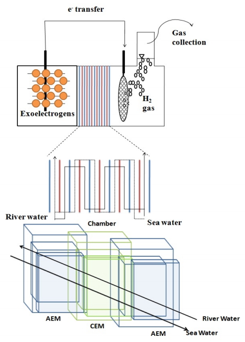
Between the anode and the cathode of a MFC can be mounted a RED cell stack. The MRC RED stack is comprised of high-and low-concentration cells segregated by AEM and CEM. The difference in concentrations which lead to salinity-based potentials in the RED stack is that anions and cations are transported from high concentrated to low-concentration cells by the RED stack which leads to salinity-led potential. In anode and cathode rooms, there are also spontaneous anodic and cathode reactions for producing bioelectricity [4]. The RED stack has enhanced the salinity-driven power supply of MRCs. It is proposed that a mixture of AEMs and CEMs can have approximately 100 mV-200 mV in different salinity levels at low-level and high concentrations. RED power can also positively affect the catalytic function of EAB and directly boost the MRC's electricity generation [84]. Essentially, the RED Stack’s salinity-driven potential allows for the spontaneous creation of hydrogen gas without an outside energy source [85].
3.5.2. Microbial reverse electrodialysis cell design construction
The first MRC reactors were fitted with a RED stack and two modified MFC chambers as discussed in Fig. 4 [4]. In most previous studies the model of the first MRC was used, and a number of MRC trials have measured major effects. Kim and Logan [85] tested different catalysts (for instance platinum, molybdenum disulphide, etc.) and electrodes (for example stainless steels and carbon clothes) in the hydrogen gas MRCs labeled with microbial reversed electrode layer. The higher production levels of hydrogen were shown by platinum capped MRC plate, while molybdenum disulfides also were a non-precious hydrogen source of carbon. MRCs such as pH reduction, chamber ion anode aggregation, carbamate ion transfer into anode chamber (used in a RED stack to create a salinity gradient using an ammonium bicarbonate solution) are constrained in their application [86,87]. Under the same conditions as MDCCs Luo et al. [86] changed the configuration of the MRC by adding a BPM in place of the AEM, known as an efficient reverse electrodialysis cell (MRCC), which decreases the pH decrease and aggregation of ions while simultaneously producing acids and alkalines.
The internal intensity of the RED stack significantly reduces power generation in the MRC so that capacity changes are not commensurate with the RED cell count. Several scientists have sought to refine the RED stack in terms of cell pairs and isolation. Cusick [84] has shown that the generation of power by constructing one or two RED cell pairs between anode and cathode could significantly improve a single chamber, that is to say a minimum RED cell pair. The MRC was then attached to a couple of RED cells and determined according to the MRC attributes and costs of energy, the number of ideal cell pairs. MRCs with five to seven pairs of RED cells showed a great energy recovery despite increased internal resistance. Nevertheless, in terms of the cost of capital, the RED stack was eventually described as the best design for MRC. Liu et al. [88] designed a patterned IEM instead of non-conductive thick spacers as a strategy to reduce the internal resistance to MRCs that are usually in the IEM of racket stacks and interfere with the movement of ion through IEMs. As the RED stake resistance with the use of patterned IEMs has decreased by 38% power density of the MRC.
3.5.3. Microbial reverse electrodialysis working conditions
The bulk of MRCs and household wastewater as the carbon source for MRCs have been used to manufacture Acetate [84]. The reduced degradability of the EAB in MRCs means that energy recycling efficiencies for household wastewater are significantly lower than those for acetate. In the continuous processing of hydrogen gas, a MRC was also used in fermenting wastewater. The amount in salinity of sodium chloride solutions with a low and high concentration was measured. Kim and Logan [4] assessed MRC efficiency in three salinity ratios (1, 50, and 100). With salinity ratio of 50, Cusick [89] and Nam [90] examined the salinity ratio effect when salinity gradient potential was generated by MRC or MRC from solutions such as ammonium bicarbonate. Cusick reported that the MRC had the highest power density when the solution for concentrations was set at 0.95 M at a salinity ratio of 100. In comparison, when the salinity ratio was adjusted to 100, the intensity of the high concentration level significantly affected the MRC's maximum power output. Sodium chloride solutions also have a considerable impact on production of MRC through a stack of REDs of low to high concentrations. For example, by increasing the flow rate from 0.85 mL/min to 1.55 mL/min, the maximum power density of a MRC is increased. According to the Hidayat [91] study, there are multivalent ions in a RED stack (e.g. magnesium and sulfate ions). The MRC received a lower level of hydrogen gas through the high and low-concentration sodium Chloride solutions for the stack RED. In terms of anolyte-related functional factors in MRCs or MRCs were examined for anolyte HR TM and the presence of a pH buffer (e.g. PBS). Next, Watson [92] as an operating feature and under constant conditions, Song [93] researched the effect of anolyte HRT. Watson indicated that a significant change in anolyte affluent and effluent COD values could increase anode capability as a result of the long HRT anolyte, which has a negative impact on output of MRC. Likewise, Song has shown that the HRT anolyte is stabler than long HRH anolyte. Song [93] also related to and without anolyte the effects of MRCs. MRC achieved a comparable level of hydrogen production without PBS, which showed that in real wastewater systems, a lack of a buffer solution could economically benefit. Through contrast, catholyte effluent could also be a good alternative to the use of PBS with the MRC anode chamber. Nam [90] explored the impact of catholyte concentration on MRC performance as a catholyte-based operating element to maximize hydrogen production in MRCs by increasing the overpotential cathode levels.
4. Challenges and possible solutions in the field
4.1. Current challenges
MESs will become versatile through the incorporation of membrane water treatment systems and energy generation techniques which will allow you to solve existing MES problems. The ultimate aim of MES-MT's work is to market MES-MT devices that can treat a large amount of real waste or salt water with high efficiency. Nonetheless, new methods are still difficult due to a number of critical problems including limited biodegradability of actual water sources and inefficient desalination of real seawater, machinery and membrane fouling, etc. We are addressing different major challenges for the production of MES-MTs in this segment [94].
4.1.1. Poor wastewater / seawater treatment efficiency
Different studies have compared the results of MES-MTs explicitly because the product output usually is measured using multiple variables that can vary considerably or are not adequately detailed to be reported by different teams of researchers. Drainage / ocean water is a big component and has very different behavior in natural drainage / seawater [19,84,89,95]. Very few experiments have used actual freshwater. Regardless of the type of MES-MT, the wastewater was used as a buffer, relative to acetates, leading to lower power densities and COD elimination. Due to the power produced by the salinity gradient of the RED stack [84] MRCs for wastewater will achieve an output capacity of approximately 70,000 mW/m3. The PF-MFC system could achieve good removal due to biological processing and membrane filtration in respect of COD extraction [96].
4.1.2. Issues concerning scaling up
The scaling up of MES-MT reactors and the attachment of several system units are currently considered as the possible solution. Nevertheless, most of the reactors designed in previous studies were millimeter sized. Just a few experiments have measured the efficiency of more liter-scale reactors. The MDC setup is imported to scale up MDCs and layered MDC setups. Similar to liter level, tested for 8 months with a solution of sodium chloride and sea salt dissolved water MDC [18]. The collection volume of the MDC upstream sample was 2.75 L. The MDC upstream in liter volume was the same as the smaller MDC upstream. In contrast to the conventional three-chamber MDC configuration the stacked MDC system improves the desalination speed and boosts the stacked MDC reactor size to 10 L. The assessment of its efficiency was carried out. The 10-L-scale MDC with stacked desalination levels of 95.4 mg/h was roughly 96 percent in batch mode.
In previous Os-MFC experiments only the Pardeshi and Mungray [97] type Os-MFC reactor was a liter size (total volume: 3 L). The emphasis was, however, on efficiency tests of the newly invented Os-MFC reactor FO membranes and reactor design does not seem to be scale up. MFC modules or elements are immersed in large volumes (i.e. greater than liter scales) of MBR or bioreactors in the development of PF-MFCs [74,76,98]. Compared to other MES-MTs, PF-MFCs appear to be easy to scale. For example, a single-compartment MFC module is equipped with an aerobic MBR reactor (total operating volume of approximately 20 L). The unit’s COD removal speed was above 93% while its power density limit was 0.053 W/m2. Recently, by linking 30 upstream MDC tubular reactors and the post aerobic process, Zhang and He [34] established a MDC network with a total volume of liquid of 105 L. When Glucose-based Synthetic Wastewater had been introduced to the network, the largest MDC system was checked under different conditions, including electrical connection, wastewater flow and applied voltage. The current generation and desalination rate were increased if industrial waste was fed at various places and an additional voltage was connected to the MDC network. The current maximum production rate of about 2,000 mA and almost 100% COD extraction and 67% salt regeneration have been accomplished by this huge MDC. This system has significantly lower efficiencies than micro-liter MDCs, but through these multi-units the efficiency of drainage and desalination has been improved across the independent system.
4.1.3. Membrane-related problems
In order to address issues currently faced by MESs, MESs can be made more robust and funded by membrane-based water therapy and energy generation technologies, but core membrane related issues have to be resolved. Membrane fouling is a crucial problem which has been confronted by various membrane-based water purification systems. The cost of capital is rising, and the efficiency of the network is decreased by fouling membranes. The biofouling of an AEM in the interaction with an anode chamber and scaling of the CEM between a desalination chamber and a cathode chamber will lead to significant decline in quality by cations, such as the cation Ca2+ and the dissolved Mg2+ in saltwater [14]. Nonetheless, significant quality deterioration was observed during long-term studies for MDC biofouling on the AEM surface. The actual desalination density and efficiency falls by 47 and 27 percent respectively compared to early MDC results in a 8-month study led by Luo et al. [14]. In addition, Ping et al. [48] reported significant decrease in current generations, mainly through increased membrane resistance during long-term surgery due to biofouling on AEM and inorganic CEM scaling.
Unlike the latter Luo et al. [14], inorganic CEM scaling mainly degraded the existing MDCs. In that same manner, Ca2+ and Mg2+, which were operated on long-lasting R-MDC [60], reduced the electrical conductivity of IERs. However, biofouling on AEM and CEM led to a significant deterioration of MDC bio-cathode performance, and a rapid regeneration in MDC performance when there was replacement of biofuels with new IEMs [50]. MDCs can substantially increase their funding costs through the use of membrane replacement. An additional problem was unfavorable mass transfer through membranes. The main deletion of COD as well as coulombic output from MDC was impaired by the diffusion in AEM during the MDC procedures. Substrate delivery can contaminate the entire membrane with desalinated water that can promote micro-organism growth. Ionic organisms like phosphate may be shipped to desalination chambers in anode chambers to reduce the efficiency of desalination. This could be most often due to increased osmotic water flow from a high-concentration gradient, resulting in an adverse reverse transfer of organic or non-organic anode contaminants into desalination chambers, in particular as MDCs are used to decrease the high water level such as seawater. Werner [13] noted that the improved permeation of reverse solvents is significantly impaired by OsMFCs because of the low level of water on the feed. The MRCs hinder sustainability and surpass the overall anode release cap for Nitrogen Crossover from RED to the anode chamber.
4.2. Possible solutions to challenges
In addition to these critical obstacles, researchers pose several other bottlenecks in the marketing of MES-MTs. The web site and the intent of the construction of materials and organic carbon supplies are linked to different factors such as reactor capacity, electrical and membrane materials. For order to achieve promotion all these considerations must be addressed together. In order to develop entire systems, the scale of electrodes has to be substantially increased thus retaining the power conductivity. In relatively harsh conditions, though, the substrate of the electrode must be economical and durable. Usually BESMTs consist of carbon-based materials and electrical metals that are inflexible. Nonetheless, because of numerous disadvantages including biomass stability, longevity, oxidation and poor electrical conductivity, these materials cannot be suitably assisted for full-scale MES-MT.
The creation of new flexible nanocomposite electrodes, leading filters using conducting polymers and carbon-based nanomaterials (such as graphene oxides), will help overcome these limitations. These materials will quickly be inexpensive as mass production technologies are rapidly improving, even as carbon-based nanomaterial prices tend to be high. This is why the analysis should be carried out of the full-scale MES-MT reactor configuration. For this reason, consideration should be given to minimal footprint, easy operation and maintenance and efficient integration of existing sewage and wastewater desalination plants. Therefore, fluid or ion movements in reactors may affect the quality of the MES-MTs significantly. A framework such as fluid dynamics should be developed to better understand these phenomena.
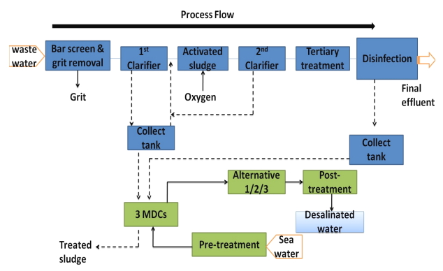
5. Desalination alternatives in the MDC integrated wastewater processing plant are identified and evaluated
After the quality analysis of several types of MDCs, the designs for a technically integrated MDC wastewater treatment plant were designed as illustrated in Fig. 5 to improve overall output and decrease electricity consumption. Include stacked MDC configurations in this system since sampling is easy, additional MDC units are attached to each other and the desalination rate is required [21].
5.1. Definition of the general process
Wastewater processing plants typically of domestic origin. A large number of methods have been developed to mitigate pollution by proper treatment of wastewater before it is released into the atmosphere. The foregoing was explored and contrasted with several proposed alternatives to a MDC wastewater treatment plant for drainage and desalination of seawater. This is described below.
5.2. 1st alternative: reverse osmosis desalination
Three MDCs are used as a reverse osmosis as a pre-desalination device (RO). Seawater is first injected into the MDC network using the granular pre-processing filter. Previous studies have shown that desalination in each cell is 50 percent. In this case, the desalination rate for salt water was improved by three series MDCs. This is accompanied by the partial desalination water being fed into a desalination cycle RO process. In a post-treatment system, the fresh water is then injected in a controlled pH system, chlorinated for drinking and medicinal purposes [99].
5.3. 2nd alternative multistage flash desalination
Three MDCs were stacked with a desalination rate of 50 percent per cell and used for pre-desalination technique. The treated water will then be supplied to the MSF column for further storage following pre-desalination. The MSF process is used for desalination in industries which handle large amounts of low-pressure salt water. Water is pumped as a heat source into salty water and falls into the first MSF desalination base. If the feed water is heated and the water filtered constantly circulates through several phases of the system, the vapor is diluted, thus completing a successful desalination process.
5.4. Assessment of alternatives to desalination
The above-mentioned two desalination solutions can be contrasted with the most viable alternative plant with matrix checking. In order to choose the best alternative, six metrics will be used, including capital cost, operating costs, waste treatment efficiency, environmental impacts and health. The value of each factor in plant selection is measured. The most important objective of the MDC-based wastewater treatment plant is absolute production of salt and low fuel consumption, as well as desalination and desalination rates. For each parameter, each alternative is graded. For each alternative, the cumulative points achieved are then summarized. The MSF desalination cycle in conjunction with the RO increased the cost of capital as a result of its high building pace.
The result is that option 1 is more important than alternative 2 with MSF because of the lower capital cost. Due to the complex processes and activities related to this model, operating costs in the cycle for a RO are typically larger. Therefore, RO's labor costs and chemical products would be raised. The MSF system also meets the RO requirement, despite lower operating costs. The facility pays money for the efficient operation of wastewater treatment facilities and MDCs [47]. The fuel cost is much greater than the cost of the RO, and therefore the proportion is smaller. The efficiency of desalination relates to the amount of salt derived from seawater wastewater plants. The TDS level of the output stream of alternative 1 is approx. 350-500 ppm, whereas the TDS level of the MSF of the output stream of the source is below 10 ppm. This is why the quality of MSF is higher than that of RO. Salt is pumped into the sea and greenhouse gas has the biggest environmental impact both in post-treatment desalination plants. The RO temperature is not significantly higher than the MSF temperature, which would have a greater environmental influence on the marine animal’s aquatic lives. But since the MSF system is using more electricity, it produces more greenhouse gas emissions [99].
Therefore, as opposed to RO, the MSF alternative is environmentally friendly; the MSF alternative has a lower ranking. Conversely, due to higher working temperature, safety concerns of the MSF desalination plant running at temperatures between 20 and 40℃ can be seen as more severe. Nevertheless, the RO system handles extremely high pressure and must also be carefully handled. Nonetheless, safety concerns are deemed to be more serious due to high temperatures and the safety rating of the MSF process is popular [100].
5.5. 3rd alternative: Desalination with solar assistance
Solar desalination reduces the power consumption of the factory. Multi-stage solar collector-assisted desalination (MEDs) should receive greater exposure. There are several processes or checks in the MED facility. In the pipes every step of the way, the feeding water is heated by steam. Some of the liquid evaporates, and enters the next stage, where more water is heated and evaporated. In every step, energy from the previous system is reused. Therefore, a solar collector can be used to pre-heat water sources in order to reduce desalination cycle energy demands [99].
A typical solar panel may be an evacuated pipeline tank. The solar basin comprises three layers of saltwater, where salt levels are elevated from top to bottom in the upper and lower layers of salt. The medium layer, however, has a salinity gradient, which inhibits heat transfer and functions as an insulating barrier. Seawater reaches the solar panel and flows into a circulating pump made up of a variety of adjacent tanks into warm water. The thermal accumulator means the temperature changes of the evaporator are not significant or that solar power is not the source of fluctuations. The evaporator is also worked at very high temperatures (e.g. 99℃) and very low pressures (e.g. 0.07 atm). The pre-heated water is pumped into the first container of the tank and the fluid entered from the first container by the evaporator is stored. It means that the water supply is optimally evaporated. The first step of a MSF Heat Interchanger is to become a liquid-fluid heat exchanger rather than a steam-liquid-heating exchanger in a solar-assisted MSF. The solar collector norm for MSF is a solar pool as salt is deposited into the waste system’s tank [100].
6. Potential applications beyond desalination, electricity production and removal of organic carbon
6.1. Desalination pre-treatment and post-treatment
MDCs and Os-MFCs are the primary potential application of pre-treatment for desalination processes, such as RO and ED, in order to reduce their demands for electricity [18,23,24]. Jacobson [18] claimed that upstream MDC and TDS feed-seawater TDS energy demands can be decreased by 20% and electricity generation can be produced. MDCs may also be used for the treatment of concentrate extracted from RO. Luo et al. [101] have tested the effectiveness of MEDCC focus RO therapy. MEDCC would need the lowest level of energy (2,85-6,14 kwh/m3), relative to other RO concentrates such as thermal evaporation, ED and electrochemical oxidation.
6.2. Precious production of chemical
In addition to uses for electricity generation and lower salinity, MES-MTs can also be used for beneficial chemical production processes. Through modifying the cathode reaction and through external energy supply, MDCs and Os-MFCs create hydrogen gas or hydrogen Peroxide in their cathode [23,71]. These are referred to as FO-based MECs. The PF-MFC style single chamber can be used to capture methane gases from low-proof wastewater with a double hollow filter membrane and cathodic reaction. MRCs can also be used for processing of hydrogen and methane gasses but the MRCs do not need an external power supply due to the gradient collected by the RED stack [85,102]. A further example of chemical production was the MEDCC, a revamped MDC using BPM, which indicates potential applications for acidic and alkaline materials. The expected economic benefits of alkaline production from the MEDCCs are high, as alkaline production maybe 7 times lower (about $0.07) than the current cost to the consumer, based on the approximate figures provided in this article [17].
6.3. Reduction of harmful substances and softening of water
Dangerous heavy metals such as chromium and copper, and hardness in desalination chambers can be removed from the MES-MT by cathodic reduction reaction and electric ion immigration. An [103] and D’Angelo [104] et al. showed a reduction of hexavalent chromium with a cathodic drop in a MRC. An [105] also revealed that the cathode-reacting copper(I) to copper(I)oxide decrease is suitable for the handling of heavy metals including copper vapor. For the production of hydroxide precipitation, Dong [106] suggested another approach for copper extraction, using alkaline waste from a cathodes chamber of stacked MDCs. This process had a production rate of almost 100% (initial copper concentration: 5 g/L). In comparison, a conventional MDC with three chambers was used by the Brastad and He [107] for the elimination from electric field ion migration of hardness and heavy metal products, such as copper and nickel. Although it took a long HRT, the removal was carried out with high performance. Boron has also been extracted with MES-MTs in addition to the reduction of heavy metals and water softening. Excessive boron penetration may be toxic and hazardous to humans. Nevertheless, the elimination of boron from seawater has remained a problem even during reverse osmosis, which is now the most successful desalination process in marine water [108].
6.4. Nutrient removal and recovery
The potential areas for MES-MTs are denitrification and nutrient recovery. A SMDDC system that can be used to adjust the MDC structure can denitrify ground water on site, use electrical fields to capture anodic soil nitrate and electrochemically reduce the number of nitrates obtained from the cathode chamber. There are no further criteria for SMDDC ground water denitrification. For the recovery and extraction of nitrogen and phosphorus from the wastewater by a stacked MDC, Chen has also developed a new microbial nutrient recovery cell (AMNRC). The desalination chambers of the AMNRC are treated sequentially through anaerobic biodegradation, aerobic cathode biodegradation and the movement of electric nutrient ions. Maximum phosphorus and nitrogen were eventually eliminated at 98.6 and 96.9%, respectively. While various bottlenecks have to be overcome for MES-MT's commercial applications [109], an increasing demand for better technologies and technological innovation will lead to a revolution for MES-MTs and new insights created [110].
7. Life Cycle Assessment (LCA) and cost estimation of MDC
Manufacturing MDCs have had larger environmental effects. A full LCA summarized in the Table 3 showed 22.7 percent significance during industrial production and 58.7 percent during global warming operations. The production of MDCs included the construction of membranes that typically contained carriers of ion exchange where the binders of polytetrafluoroethylene (PTFE) often attributed to emissions. And the operational impacts were related to the electricity needed for the continuous water pumping. The significantly higher environmental implications of the system production are primarily due to the polytetrafluoroethylene (PTFE) binder and to fabricate ion-exchange membranes, whereas the major environmental influences mostly during MDC process are due to the power consumption for water pumping i.e. 0.1 kW/m3anode including the membrane maintenance costs in the MDC process due to the biofouling issue. At the current stage, electricity generation from the MDC is relatively low, and further enhancing the power density is imperative to enhance the functionality and improve the MDC technology’s environmental performance [111].
The cost estimation along with various other parameters like energy consumption has been discussed in Table 4.
8. Conclusion
MDC is a futuristic technology that can minimize power consumption and can act as desalination source if installed as pre-treatment units during water treatment. MDC can produce its own electricity while treating wastewater and desalinating water simultaneously by exposing the waste matter present in water to exoelectrogenic bacteria. There are various modifications carried out by integrating MDC with other membrane-based technologies to reduce the limitations observed in conventional MDC systems, which has been summarized in Table 5. These integrated systems showed promising results in reducing the limitations discussed in this review but, further research on its scale up is required on the basis of economic feasibility of the process along with environmental sustainability for commercialization of this technology. Even though the cost of desalinating using MDC technology is costly because of the part assembly and construction but will drastically reduce due to mass production of these components.